YANG models used in TransportPCE
East/West APIs YANG models
Transport PCE is based on a modular structure. Some of the bundles are tightly connected to the type of equipment handled by the controller. This is the case of the Renderer and the OLM that allow configuring OpenROADM equipment. Thus the algorithms of the different functions they implement, respect the procedure defined in the OpenROADM Device white paper.
Some other modules are less tightly coupled to the type of controlled equipment, such as the PCE and the Topology discovery. To ease further evolution Transport PCE specific models are published on the following Github repository: https://github.com/transportPCE/transportPCE_Public
Published models define a common base allowing the different modules to share the information present in the DataStore and to communicate. They can be used as a reference by contributors to develop complementary/additional features. These new features as far as they rely on the reference model could be triggered from existing module, in place of others having the same functionality for different kind of equipment, or to complement existing functions.
As an example we could imagine extending the support of equipment following different models. This would imply to develop some specific OLM & Renderer to configure the devices and to extend the topology model through additional augmentations.
OpenROADM YANG models
Overview
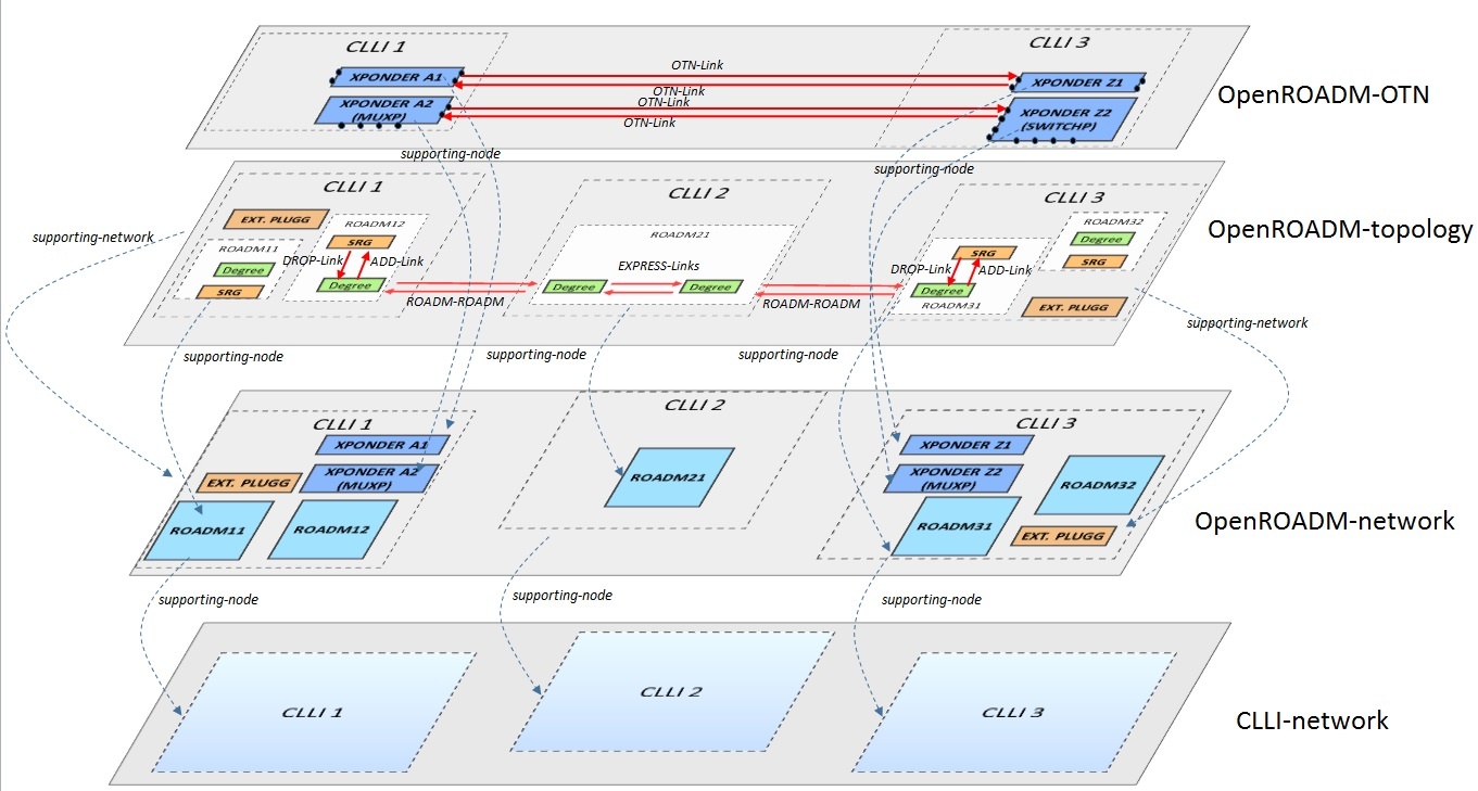
OpenROADM Device and Network Models have been presented by AT&T: Open_ROADM_Models_v0_2.pdf
Full models can be retrieved following OpenROADM website (download section).
Initial Discussion around RFC 7446
Orange (XP) review- Aditional review by other contributors is welcome.
Static information
Connectivity matrix
Section 4.1 specifies a connectivity matrix indicating which input port could possibly be connected to which output port. This is similar to the connectivity-map in openroadm network model with still some differences in presenting data.ressource pool
As far as I understand this part, it is related to regenerators or wavelength converters. As far as Orange is concerned, these functions are not taken into consideration in ROADM modeling. If regeneration is needed/preferred, it is up to the PCE to decide where to make it taking into consideration ROADM, transponders, and OTN switches. One could say that two transponders back to back become a regen/converter, but the two transponders can also be used without being back to back. Therefore, it seems to me more adquate to have the granularity of transponder and let the PCE decide whether associating 2 of them or not.Link information
This part is fundamental for PCE and shall be described in the link part of I2RS model structure. As far as OTN/WDM are concerned, links can either be OTUx or LO-ODUx. Most of the information described in section 6 is relevant. Port label restrictions are still vague to me.Dynamic information
Agreed with dynamic link information even if bandwidth (for LO-ODU) should be added. For node information, it is related to resource pool and therefore probably not relevant.Synthesis
Information related to links shall be modeled in the link part of I2RS model structure and there is no real reason for diverging with RFC 7446. It will however enriched with additional information in order to perform accurate path feasibility calculation or to ensure some service metrics are checked. Regarding node description, I am not sure to see how they can really converge. One model is de-aggregated for accurate path calculation (typically for disjointness requirements) while it may be diificult to derive one de-aggregated from RFC 7446. Besides, the notion of resource pool does probably not meet the needs for the reason given here above (transponder can be used for regen or not).
Ericsson (FL) commentActually, resource pool is a more complex and general concept, as it's a modular and versatile blocks based approach. Its aim is to model any connectivity limitation inside a node, and is applicable not only to ROADMs, but also to other technologies, typically to model connectivity limitations of multiple technologies NEs, like a NE having both OTN and WDM switching capabilities (e.g. Ericsson SPO family has exactly this capabilities, and also allows to add SDH and packet switching altogether).
When some ports can be connected with a subset of the other ports available inside the NE, and possibly the guaranteed connectivity has also limitations (e.g. there is a limit on the maximum switchable bandwidth) this model can be very useful.
Besides, resource pool is not limited to regeneration and wavelength conversion. There are other cases where this is useful :
- Modeling of transponders "add/drop" of a single line (fixed connectivity to the relevant line only)
- Modeling of transponder sharing mechanisms (connectivity to an intermediate stage allowing directionless/colorless/contentionless routing). Occupation of the intermediate sharing hardware must also be taken into account when assigning or verifying lambdas.
The intermediate sharing stage can be in turn connected to all or part of the line interfaces of the NE, and once again this can be done effectively with the resource pool mechanism.
- Lambda limitations on internal HW (beside the case highlighted at the previous point); e.g. lambda limitations due to transponder ports, filters or other equipment configured on the NE.
Resource pool concept is based on two types of objects:
- Resource blocks, representing a general set of internal NE resources, and keeping track of their capabilities, occupation and relationship with external interfaces (the traffic ports of the NE)
- Connectivity matrixes, representing actual connectivity between resource blocks.
This way it's possible in a very comprehensive and detailed way to model the internal structure of a generic NE with its real limitations, taking into account their current usage.
I understand that the other model is more focused on WDM NEs, and possibly less general. Deciding whether to use one of the other would require to do a more detailed use case analysis, taking into account real NE scenarios, not only in WDM domain but also in OTN (at least) as this is an additional target of the project.
From OpenROADM network model to an I2RS compatible topology description
The I2RS draft version (4) can be retrieved at https://tools.ietf.org/html/draft-ietf-i2rs-yang-network-topo-04